rfid passive tag block diagram The block diagram of the proposed passive RFID tag is presented in Fig. 1. The system is composed by the following blocks: Rectifier – The RF signal received by the antenna is . Make sure you've accounted for a 2mm bleed in your design; this is where your .
0 · smallest passive rfid tag
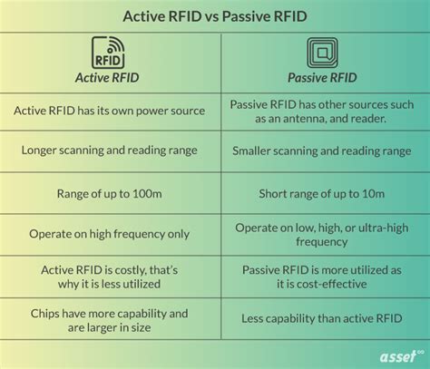
1 · rfid tags passive vs active
2 · rfid passive tag cost
3 · range of passive rfid tags
4 · passive rfid tags for sale
5 · passive rfid tag price
6 · passive rfid tag example
7 · long range passive rfid tags
Learn how you can add digital keys in Samsung Wallet for Door Lock or Car on Samsung Galaxy S23/S23+/Ultra.This demonstration is running on Android 13.To Don.Posted on Nov 1, 2021 12:10 PM. On your iPhone, open the Shortcuts app. Tap on the Automation tab at the bottom of your screen. Tap on Create Personal Automation. Scroll down and select NFC. Tap on Scan. Put .
smallest passive rfid tag
The passive tag absorbs a small portion of the energy emitted by the reader, and starts sending modulated information when sufficient energy is acquired from the rf field generated by the . When looking into implementing a passive RFID tag system into your business, one of the most important diagrams to have is the passive RFID tag schematic diagram. This .The passive tag absorbs a small portion of the energy emitted by the reader, and starts sending modulated information when sufficient energy is acquired from the rf field generated by the .
When looking into implementing a passive RFID tag system into your business, one of the most important diagrams to have is the passive RFID tag schematic diagram. This .
The block diagram of the proposed passive RFID tag is presented in Fig. 1. The system is composed by the following blocks: Rectifier – The RF signal received by the antenna is .
2. Passive RFID system: This is the most commonly used type of system that you can find in ID cards, banking cards etc. It consists of passive tags which doesn’t have any .The block diagram of a UHF RFID transponder is shown in figure 1, it consists of an antenna, a digital part, and an analog front-end part contains, a modulator, a demodulator and an.However, a passive UHF RFID system has challenges in tagging a metallic object due to effects of conducting materials on the tag antenna performance. This study presents investigation and.
The block diagram of an RFID system is shown in Fig. 1 (a). In this technol- ogy the reader sends data to the tag using RF waves and in return receives a modulated echo simulating the.
RFID = Radio Frequency IDentification. An ADC (Automated Data Collection) technology that: uses radio frequency waves to transfer data between a reader and a movable item to identify, .Passive RFID Tags. Passive RFID tags contain a low-power integrated circuit (IC) attached to an antenna, and are enclosed with pro-tective packaging (like a plastic card) as determined by .
The following figure shows a classic block diagram of an UHF-RFID tag. There are two main parts : The antenna : It converts the electromagnetic waves into data and energy for .The passive tag absorbs a small portion of the energy emitted by the reader, and starts sending modulated information when sufficient energy is acquired from the rf field generated by the . When looking into implementing a passive RFID tag system into your business, one of the most important diagrams to have is the passive RFID tag schematic diagram. This .The block diagram of the proposed passive RFID tag is presented in Fig. 1. The system is composed by the following blocks: Rectifier – The RF signal received by the antenna is .
2. Passive RFID system: This is the most commonly used type of system that you can find in ID cards, banking cards etc. It consists of passive tags which doesn’t have any .The block diagram of a UHF RFID transponder is shown in figure 1, it consists of an antenna, a digital part, and an analog front-end part contains, a modulator, a demodulator and an.

rfid tags passive vs active
However, a passive UHF RFID system has challenges in tagging a metallic object due to effects of conducting materials on the tag antenna performance. This study presents investigation and.The block diagram of an RFID system is shown in Fig. 1 (a). In this technol- ogy the reader sends data to the tag using RF waves and in return receives a modulated echo simulating the.RFID = Radio Frequency IDentification. An ADC (Automated Data Collection) technology that: uses radio frequency waves to transfer data between a reader and a movable item to identify, .Passive RFID Tags. Passive RFID tags contain a low-power integrated circuit (IC) attached to an antenna, and are enclosed with pro-tective packaging (like a plastic card) as determined by .

Near-field communication (NFC) is a set of communication protocols that enables communication between two electronic devices over a distance of 4 cm (1+1⁄2 in) or less. NFC offers a low-speed connection through a simple setup that can be used for the bootstrapping of capable wireless connections. Like other proximity card technologies, NFC is based on inductive coupling between two electromagnetic coilsNFC, or near-field communication, is a short-range wireless technology that allows your phone to act as a transit pass or credit card, quickly transfer data, or instantly pair with Bluetooth .
rfid passive tag block diagram|long range passive rfid tags