rfid card schematic RFID Block Schematic: A simplified block schematic of an RFID tag (also called transponder) is shown in the diagram below. Various components of the tag are as shown.
Central Alabama NOAA Weather Radio (NWR) There are 10 weather radio .
0 · rfid with arduino code
1 · rfid tag block diagram
2 · rfid schematic diagram
3 · rfid rc522 with arduino
4 · rfid rc522 interfacing with arduino
5 · rfid rc522 arduino mega 2560
6 · rfid circuit diagram explanation
7 · how to connect rfid arduino
3. Swipe down from the top-right corner of the screen (on iPhone X) or swipe up from the bottom of the screen (on older iPhones) to access the Control Center and tap the NFC Tag Reader option. After that, try scanning a .
This section is written for RF coil designers and RFID system engineers. It reviews basic electromagnetic theories on antenna coils, a procedure for coil design, calculation and .Radio Frequency Identification (RFID) systems use radio frequency to identify, locate and track people, assets and animals. Passive RFID systems are composed of three components – a .Radio Frequency Identification (RFID) systems use radio frequency to identify, locate and track people, assets and animals. Passive RFID systems are composed of three components – a reader (interroga-tor), passive tag and host computer. The tag is com-posed of an antenna coil and a silicon chip that includes basic modulation circuitry and non .This section is written for RF coil designers and RFID system engineers. It reviews basic electromagnetic theories on antenna coils, a procedure for coil design, calculation and measurement of inductance, an antenna tuning method, and read range in RFID applications. 2003 Microchip Technology Inc.
Radio Frequency Identification (RFID) systems use radio frequency to identify, locate and track people, assets and animals. Passive RFID systems are composed of three components – a reader (interroga-tor), passive tag and host computer. The tag is composed of an antenna coil and a silicon chip that includes basic modulation circuitry and .
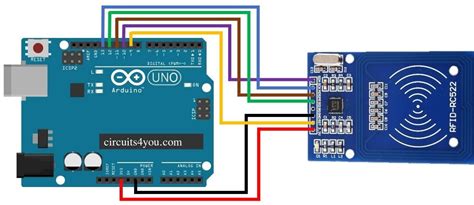
RFID Block Schematic: A simplified block schematic of an RFID tag (also called transponder) is shown in the diagram below. Various components of the tag are as shown. In this tutorial, we discussed how the RFID Reader Module works and how we can use it with Arduino. For Interfacing RFID Reader Module RC522 with Arduino, we have provided Circuit Connection, Arduino Code, and a step-by-step guide.Inside An RFID Card. RFID cards communicate with card readers using electromagnetic frequencies. When a card is held within the electromagnetic field created by a card reader, the antenna draws power from the field and funnels it to the card’s Integrated Circuit (chip). This powers on the card.
RC522 RFID Reader Module Pinout diagram, Pin Configuration details, Interfacing with Arduino Example, Applications, Features, Datasheet.
In this tutorial, we are going to interface RDM6300 RFID Reader Module with Arduino Nano. The RDM6300 RFID Reader is one type of RFID module with a 125 kHz frequency. This RFID module can read data from 125 kHz compatible read .Learn to interface RFID reader RDM6300 RDM630 modules with Arduino, examples to read RFID number from cards and display on serial monitor A RFID circuit diagram is a graphical representation of the components used in a particular RFID system. It typically includes the antenna, reader and tags, as well as other components such as power supplies, logic gates, and amplifiers.Radio Frequency Identification (RFID) systems use radio frequency to identify, locate and track people, assets and animals. Passive RFID systems are composed of three components – a reader (interroga-tor), passive tag and host computer. The tag is com-posed of an antenna coil and a silicon chip that includes basic modulation circuitry and non .
This section is written for RF coil designers and RFID system engineers. It reviews basic electromagnetic theories on antenna coils, a procedure for coil design, calculation and measurement of inductance, an antenna tuning method, and read range in RFID applications. 2003 Microchip Technology Inc.Radio Frequency Identification (RFID) systems use radio frequency to identify, locate and track people, assets and animals. Passive RFID systems are composed of three components – a reader (interroga-tor), passive tag and host computer. The tag is composed of an antenna coil and a silicon chip that includes basic modulation circuitry and .RFID Block Schematic: A simplified block schematic of an RFID tag (also called transponder) is shown in the diagram below. Various components of the tag are as shown. In this tutorial, we discussed how the RFID Reader Module works and how we can use it with Arduino. For Interfacing RFID Reader Module RC522 with Arduino, we have provided Circuit Connection, Arduino Code, and a step-by-step guide.
Inside An RFID Card. RFID cards communicate with card readers using electromagnetic frequencies. When a card is held within the electromagnetic field created by a card reader, the antenna draws power from the field and funnels it to the card’s Integrated Circuit (chip). This powers on the card.
rfid with arduino code
rfid tag block diagram


RC522 RFID Reader Module Pinout diagram, Pin Configuration details, Interfacing with Arduino Example, Applications, Features, Datasheet.
In this tutorial, we are going to interface RDM6300 RFID Reader Module with Arduino Nano. The RDM6300 RFID Reader is one type of RFID module with a 125 kHz frequency. This RFID module can read data from 125 kHz compatible read .
Learn to interface RFID reader RDM6300 RDM630 modules with Arduino, examples to read RFID number from cards and display on serial monitor

rfid schematic diagram
rfid rc522 with arduino
Fully-featured cross-platform FREE NFC SDK (µFR Series NFC Reader SDK), suitable for fast application development. RFID NFC Reader/Writer designed for advanced users and developers. NFC tag emulation, controllable RGB LED .
rfid card schematic|rfid rc522 interfacing with arduino