rfid tag proximity sensor circuit What is an RFID used for? RFID tags are a type of tracking system that uses radiofrequency to search, identify, track, and communicate . See more Views 6.8k. Participants 6. I'm using Core NFC framework in my app. We need to read credit card number, expiry date when I tap the NFC Credit card on the iPhone on which my app is .
0 · rfid tags and sensors
1 · rfid sensor cost
2 · rfid proximity detector
3 · rfid card vs proximity
4 · hid vs rfid
5 · battery assisted passive rfid tags
6 · allen bradley sensaguard sensor
7 · allen bradley safety proximity sensor
Samsung Galaxy S24+ (SM-S9260) Samsung Galaxy S24 Ultra (SM-S9280) Samsung Galaxy .That’s precisely what you will be able to do with NFC Enabled, Contactless Digital Business .
rfid tags and sensors
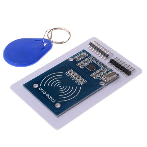
The RC522 module has a total of 8 pins. This module supports various communication protocols and each pin has a different function for each communication protocol. The pinout of a RFID Reader moduleis as follows: SDA SCLI2C Communication pins. DATA and CLOCK. SS SCK MOSI . See moreThe Schematic diagram for the RC522 moduleis given below. The circuit consists of bare minimum components. As we know the main component is the MFRC522 chip. The remaining components form the EMI filter along with the matching circuit . See more

where to find nfc tags free
What is an RFID used for? RFID tags are a type of tracking system that uses radiofrequency to search, identify, track, and communicate . See moreThe RC522 RFID module is based on the popular MFRC522 RFID reader chip from NXP These modules are cheap and available from most . See moreThe RFID system is comprised of two components: the RFID reader and the tags. They are also called PCD (Proximity Coupling Device) and PICC (Proximity Integrated Circuit . See more
With the RFID tag assembled, it’s time to test its functionality. Power up your circuit and bring an RFID tag near the RFID module’s antenna. The Arduino should read the unique . The RFID reader will check for any tags in the vicinity and if a tag is found, the reader will read the Unique ID from the tag. And if the UID matches with the UID in the code, the Arduino will toggle the LED state.
With the RFID tag assembled, it’s time to test its functionality. Power up your circuit and bring an RFID tag near the RFID module’s antenna. The Arduino should read the unique identifier of the tag and display it using the Arduino IDE’s Serial Monitor or any other output method you have programmed.When the antenna of an RFID tag comes into close proximity to a metallic or high-detuning object, it detunes the antenna in a similar fashion. In this case, passive sensors can adjust their own internal capacitance to best match the detuned antenna, resulting in changes to the sensor code.Tags cannot actually detect anything. They are pieces of silicon with a radio antenna attached. Sometimes, they have a battery enabling them to broadcast a signal. And if they have an onboard sensor, they can sense temperature, humidity, movement and so on.
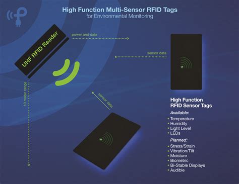
In this tutorial, we are going to learn how to use RFID/NFC with Arduino. The RFID/NFC system includes two components: reader and tag. There are two popular RFID/NFC readers: RC522 and PN532 RFID/NFC reader. This tutorial focuses on RC522 RFID/NFC reader. Using an Arduino board, a common RFID reader (MFRC522), and a few RFID tags/cards, we will be exploring methods for reading and writing RFID information in an attempt to understand how RFID communication works and identify the limits of the technology with Arduino.The I2C NFC/RFID Module will poll for tags every 350 ms. Once the module finds a tag, it drives a GPIO line low to signal the master that the tag data is ready to be read. RFID sensor tags consist of an antenna, a radio frequency integrated circuit chip (RFIC), and at least one sensor. An ideal tag can communicate over a long distance and be seamlessly.
Introduction. The ST25 NFC (near field communication) and RFID (radio frequency identification) tags extract their power from the reader field. The tag and reader antennas are inductances mutually coupled by the magnetic field, similarly to a voltage transformer (see Figure 1).Tuning the RFID tag to resonate at the carrier frequency produces the maximum communication range. This tuning is accomplished by matching the antenna inductance The RFID reader will check for any tags in the vicinity and if a tag is found, the reader will read the Unique ID from the tag. And if the UID matches with the UID in the code, the Arduino will toggle the LED state. With the RFID tag assembled, it’s time to test its functionality. Power up your circuit and bring an RFID tag near the RFID module’s antenna. The Arduino should read the unique identifier of the tag and display it using the Arduino IDE’s Serial Monitor or any other output method you have programmed.
When the antenna of an RFID tag comes into close proximity to a metallic or high-detuning object, it detunes the antenna in a similar fashion. In this case, passive sensors can adjust their own internal capacitance to best match the detuned antenna, resulting in changes to the sensor code.Tags cannot actually detect anything. They are pieces of silicon with a radio antenna attached. Sometimes, they have a battery enabling them to broadcast a signal. And if they have an onboard sensor, they can sense temperature, humidity, movement and so on.In this tutorial, we are going to learn how to use RFID/NFC with Arduino. The RFID/NFC system includes two components: reader and tag. There are two popular RFID/NFC readers: RC522 and PN532 RFID/NFC reader. This tutorial focuses on RC522 RFID/NFC reader.
Using an Arduino board, a common RFID reader (MFRC522), and a few RFID tags/cards, we will be exploring methods for reading and writing RFID information in an attempt to understand how RFID communication works and identify the limits of the technology with Arduino.The I2C NFC/RFID Module will poll for tags every 350 ms. Once the module finds a tag, it drives a GPIO line low to signal the master that the tag data is ready to be read. RFID sensor tags consist of an antenna, a radio frequency integrated circuit chip (RFIC), and at least one sensor. An ideal tag can communicate over a long distance and be seamlessly.Introduction. The ST25 NFC (near field communication) and RFID (radio frequency identification) tags extract their power from the reader field. The tag and reader antennas are inductances mutually coupled by the magnetic field, similarly to a voltage transformer (see Figure 1).
rfid sensor cost
rfid proximity detector
what is an nfc tag on android
rfid card vs proximity

January 4, 2021 • 2:43 pm PST. The 2021 NFL playoffs begin on Jan. 9 and 10 with an expanded wild-card round featuring six total games rather than the usual four. An additional seed in each .
rfid tag proximity sensor circuit|hid vs rfid